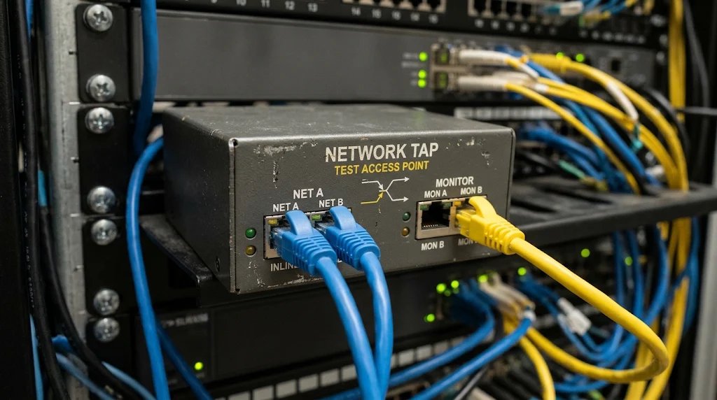
How a Network Tap Works
To understand how a network tap operates, consider a standard network connection where Device A communicates with Device B. Normally, a single cable connects the two. To deploy a tap:
- The original connection is broken, and the tap is inserted in the middle.
- Device A is connected to one port on the tap (often labeled NET A), and Device B is connected to another (labeled NET B).
- The tap passively passes all traffic back and forth between these ports, appearing completely invisible to the rest of the network—it does not have its own IP or MAC address.
- Concurrently, the tap uses internal circuitry (or optical splitters, in the case of fiber optics) to duplicate the signals. It sends these duplicates to one or more MONITOR ports, which are connected to packet analyzers, intrusion detection systems (IDS), or data recorders.
               ┌──────────────────────────────────────────────┐
               │         NETWORK TAP (TEST ACCESS POINT)       │
               │                                              │
[ Device A ] ──┼──► [ NET A ] ──(Zero Loss In-Line)──► [ NET B ] ◄──┼── [ Device B ]
               │         │                                │   │
               │         └───(Duplicated Tx Stream)───┐   │   │
               │         ┌───(Duplicated Rx Stream)───┼───┘   │
               │         ▼                            ▼       │
               │     [ MON A ]                    [ MON B ]   │
               └─────────┬────────────────────────────┬───────┘
                         │                            │
                         ▼                            ▼
                 [ Packet Sniffer ]          [ Intrusion Detection ]
Primary Hardware Tap Architectures
There are two primary types of hardware taps:
- Passive Taps: Used primarily for fiber-optic links, these require no electrical power. They use physical splitters to divert a portion of the light signal to the monitor ports. Because they have no active components, they are highly reliable and cannot fail even if power to the facility is lost.
- Active Taps: Used for copper (Ethernet) links, these require power to regenerate and copy the electrical signals. Many active taps feature bypass circuitry, ensuring that if the tap loses power, the primary "inline" connection (NET A to NET B) remains connected so network traffic is not disrupted.
Typical Use Cases and Usage
Network taps are widely used in enterprise networks, data centers, testing environments, and by cybersecurity teams. Their primary applications include:
- Troubleshooting and Performance Monitoring: When network issues like latency, packet loss, or configuration errors occur, administrators connect packet sniffers to the tap's monitor ports to inspect the exact packets passing through the wire.
- Intrusion Detection and Security Forensics: Security appliances (like IDS or network detection and response tools) rely on taps to inspect traffic for signs of malware, unauthorized access, or data exfiltration without altering the traffic or alerting an adversary.
- Regulatory Compliance and Data Recording: Industries with strict compliance requirements use taps to feed network data to continuous recording systems, capturing data for audit trails or security investigations.
Network Taps vs. Port Mirroring (SPAN)
Network administrators can also capture traffic using a switch’s software-based SPAN (Switch Port Analyzer) or port mirroring feature. However, SPAN has limitations. Under heavy traffic, a network switch will prioritize routing original data over generating duplicates, which can lead to dropped packets on the mirror port. Additionally, SPAN can consume switch CPU resources and fail to capture physical-layer errors.
Because network taps capture 100% of full-duplex traffic at the physical layer, they are preferred for high-stakes environments where missing even a single packet could create a blind spot.
| Feature Dimension | Hardware Network Tap | Switch Port Mirroring (SPAN) |
|---|---|---|
| Capture Architecture | Dedicated Layer 1 physical hardware bridge | Software-configured switch feature (SPAN/RSPAN) |
| High-Traffic Reliability | 100% full-duplex throughput; no drops | Drops duplicate packets when switch CPU/buffer saturates |
| Switch CPU Impact | Zero resource consumption on network switches | Consumes switch processing cycles and internal memory |
| Layer 1 Error Capture | Captures runt frames, CRC/FCS errors, alignment faults | Discards physical-layer error frames prior to mirror buffer |
| Attack Surface | No IP or MAC address; completely unroutable | Addressable switch management interface subject to compromise |
Privacy, Security, and Governance
A network tap is an incredibly powerful tool because it can reveal granular technical details, such as which devices are communicating, when traffic is flowing, and how much data is moving. Importantly, if the communications are encrypted (such as HTTPS web traffic), copying the packets via a tap does not decrypt the payloads; however, metadata (like IP addresses and connection timing) remains visible.
Because a tap can expose sensitive, unencrypted communications, its use carries significant responsibility:
- Authorization: Taps should be installed only by authorized personnel on networks they have explicit permission to monitor.
- Data Safeguards: Captured packets must be securely stored, encrypted, and accessible only to trusted administrators to prevent unauthorized eavesdropping.